TS Dash supports both digital Input and Output with Raspberry Pi GPIO. The state of configured Input and Output pins can then be represented by an Output Channel for display on a dashboard or in a data log. Here we will demonstrate the configuration of a digital Out and digital In.
Digital Out
In this demonstration of configuring a Digital Out, we will create a Shift light where TS Dash will light an LED when the engine speed reaches 6000 RPM.
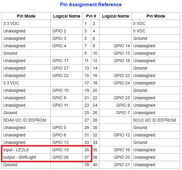
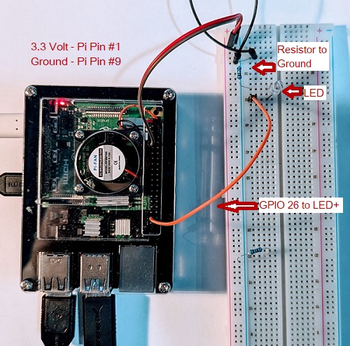
Starting with the wiring, we select a Raspberry Pi pin to use. In this case we will use GPIO 26 which is found on the 40 Pin connector in position 37. We will connect that to the positive side of the LED. The negative side of the LED will be connected to to ground through a resistor to limit current. The connected 3.3 volt wire is not used in this case even though it is connected as we are going to supply the 3.3 volts from GPIO 26.
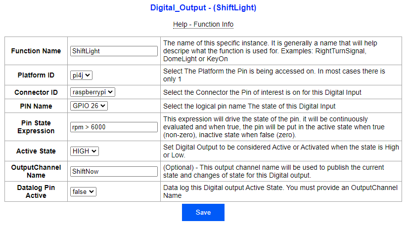
Now in the TS Dash configuration site we go to the Pin Management Page were we can configure GPIO 26 as a Digital Output controlled by TS Dash. On the Pin Management Page, we start by clicking on "Add new" under "Digital_Output". This takes us to where GPIO 26 can be set up as a Digital Output. We assign the function name of "ShiftLight" and assign GPIO 26. The expression assigned to drive the state is "rpm > 6000" and assign Active State to "HIGH". With this configuration, TS Dash will keep GPIO 26 in a low state when the expression is not true and a high state when it is true. In this case the pin will be held high when RPM's are greater than 6000 and Low when RPM's are lower than or equal to 6000 RPM. We also assign the optional OutputChannel name of "ShiftNow" so we can later configure a dashboard indicator to show the LED state.
 Note: You could also set the Active state to LOW and connect GPIO 26 to the ground side of the LED and supply continuous 3.3v to positive side of the LED. In this scenario, GPIO would be held high when the expression is false, and low when the expression is true acting as a ground to complete the circuit.
Click Save and you will return to the "Pin Management" Page. There will be a notice of "Changes require restart to take effect"

By Clicking "Reinitialize Now", the TS Dash app will be restarted. It will not trigger a full reboot of the Pi.
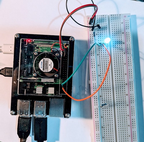
Your shift light should now be operational. If you raise the RPM's over 6000, the LED will light. Below 6000 and the LED will be off.
Digital In
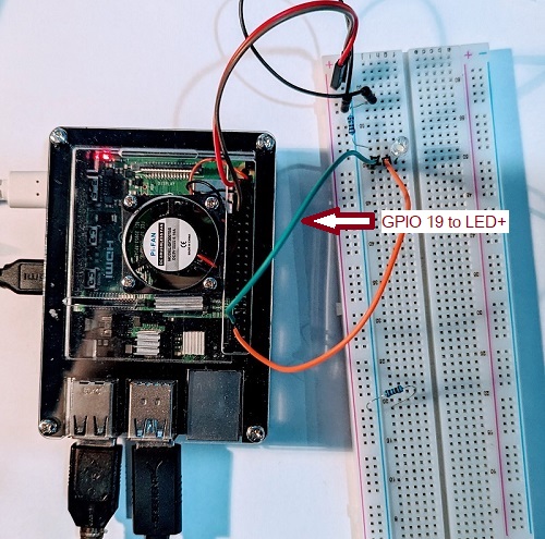
For our Digital In example, we will build upon our Digital Out by adding a wire connected to GPIO 19 (Raspberry Pi Pin# 35) that will monitor the state of the LED. Thus, when GPIO 26 goes high and lights the LED, it will also drive GPIO 19 high changing the state of the Output Channel we assign to our Digital In.

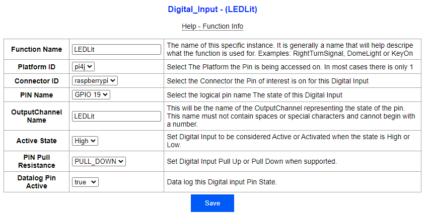
Now in the TS Dash configuration site we go to the Pin Management Page were we can configure GPIO 19 as a Digital Input monitored by TS Dash. On the Pin Management Page, we start by clicking on "Add new" under "Digital_Input". This takes us to where GPIO 19 can be set up as a Digital Input. Here we assign a Function Name of LEDLit and assign the Pin GPIO 19. For inputs, the Output Channel name is required as that is the entire point in a digital in, creating an OuputChannel that represents the state of a pin. That OuputChannel can then be used for dashboard indicators or used in expressions to drive other functions or actions. For this example, we assign the Output Channel name "LEDLit" and an Active state of "HIGH" to match that assigned to the Digital Out we created above.
Click Save and you will return to the "Pin Management" Page. There will be a notice of "Changes require restart to take effect"
By Clicking "Reinitialize Now", the TS Dash app will be restarted. It will not trigger a full reboot of the Pi.
Your Digital In should now be functioning. The Output Channel LEDLit will represent the state of GPIO 19 with a value of 1 when the LED is lit and a value of 0 when it is not. To see this, we will set up an indicator on a dashboard to light when the LED is on. While we are at it, we will also create an indicator that is assigned to the optional OutputChannel we assigned to our Digital Out on GPIO 26. To do so we will go into Dashboard Designer Mode:
- Go to the dashboard of your choice in TS Dash.
- Right click on the dashboard and select "Designer Mode"
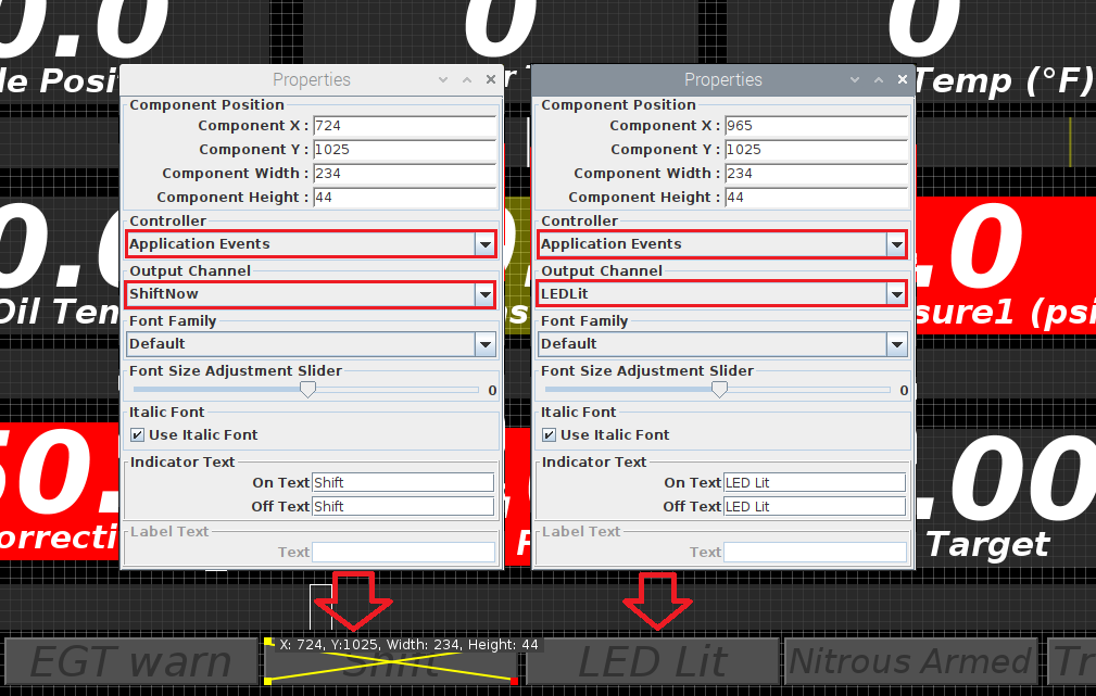
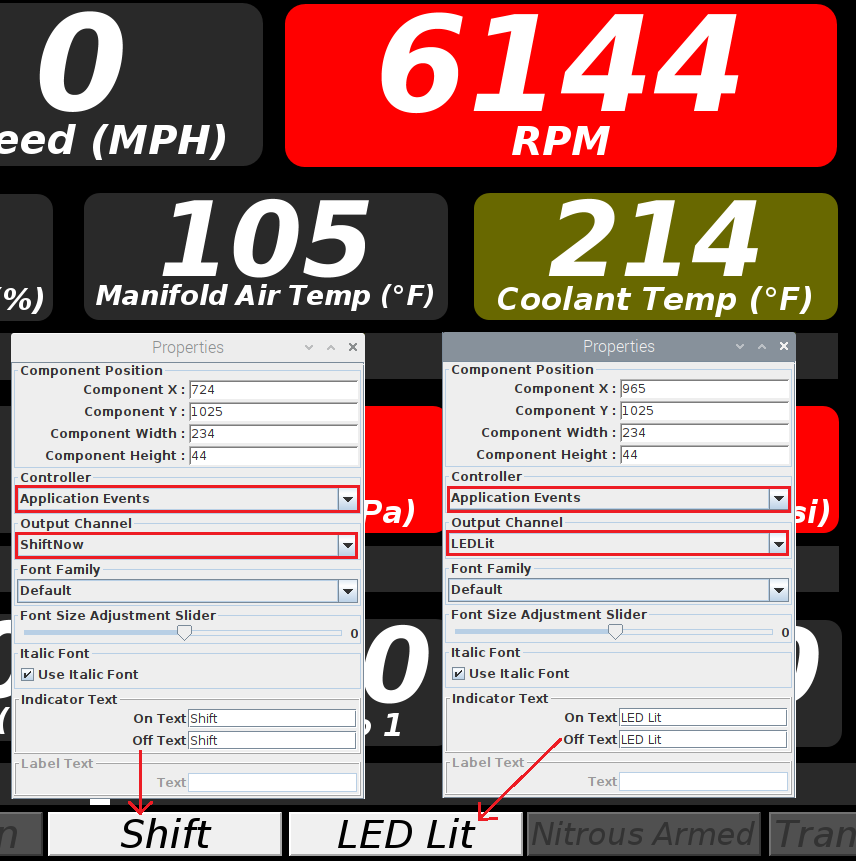
- Right Click the indicator your want to use, select "Dashboard Designer" --> "Properties Dialog"
- Under Controller, select Application Events
- Now, under Output Channel select the Output Channel we assigned to the digital in "LEDLit"
- Change the Indicator Text to something more appropriate such as "LED Lit"
- Repeat the process for the Output Channel ShiftNow that we assigned to our Digital Output
- Right Click on the dashboard and uncheck "Designer Mode"
Now, not only the LED will light up when we exceed 6000 RPM, but both indicators will light on the dashboard as well.
Below 6000 RPM:
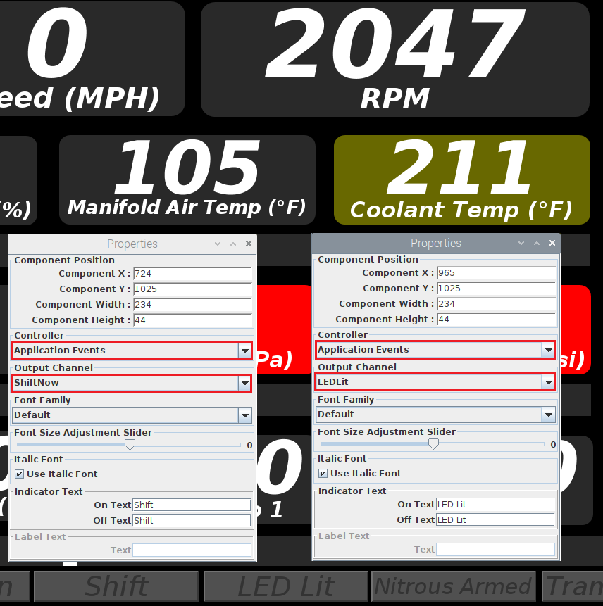
Over 6000 RPM:
On each of the Pin Management editing page, you will be able to see the pins assigned.